Introduction
There is something missing in most kitchens I have seen in my life and it is not a huge free space or a smart refrigerator. It is much simpler than that. I am talking about good lighting. All kitchen that I have used had decent lighting when used during a bright shiny day but was lacking appropriate lighting during a rainy days or nights. Most of then were also missing under cabinet lighting.
It has been a long time since I wanted to get more light available under the kitchen cabinets. However, I never felt ready to install some lights by myself for many reasons. One of them was that I was missing the proper tools and knowledge. I also didn’t like the idea of drilling holes in the cabinet or through the kitchen counter to get the electricity and finally, when I was looking at a kitchen with under cabinet lights, the lights that were used was producing too much heat that I could almost burn myself. This project was “on hold” until a super easy to install solution came to my mind: LED strips.
LED strips are an alternative to fluorescent, halogen or xenon lights. LED are becoming more and more popular and are super easy to install and adapt to many situations. Some LED strips can be used outside too but that is for another post! They provide the following benefits in a kitchen:
- Cheap!
- Give a proper lighting.
- Can be dimmed to low levels.
- Available in multiple colors like warm white or cold/cool white.
- Do not produce any heat (almost).
- Do not burn or has a much longer life time than normal lights.
- Operates at 12 volts. No need for wall AC current which could lead to accidents.
- Use less electricity (much fewer current than alternative lighting options).
In this post, I will explain how I installed in my kitchen a custom under cabinet LED lighting solution.
Note: Handling wall electricity can be dangerous. If you do not have basic electricity skills, I strongly recommend that you do not complete this project. Proceed at your own risk.
Project data
Equipment
The material for this project is as follows:
- A 5 meters LED strip.
- 2 pin Connector Wire Cable For 3528 Single Color LED Strips (5 times)
- A 36 Watts (12 volts, 3 amps) power supply.
- A 3 pins wall outlet power cord.
- A LED dimmer module.
- A wall switch.
- 2-3 meters of colored (red & black) wire.
- Double sided tape
- Sticker gum
- A multimeter (for testing connections and power output)
- Screws
- A Phillips screwdriver
- Flexible measuring tape
Power supply
Theoretically, only a 24 Watts power supply is required for powering the whole LED strip. However, I usually feel more comfortable when I get more power than I will need. It is also better for the power supply to not always power the LED strip at maximum current during longer period of time.
Dimmer module
The dimmer module is optional but I strongly recommend to use one. Without the dimmer module, the LED strip is too bright for many situations. Full brightness is only required for cutting vegetables. For all other scenarios, you will need to reduce the intensity of the light if you want to create ambient lighting during the night or if you need a low-light in the morning. Even a warm white (compared to a cool/cold white) strip is too bright when I get out of the bed. Anyway, for the price of the module, it should be a no brainer.
Please note that a “normal” wall dimmer cannot be used to power the LED strip since LED can only be dimmed with a PWM module and not by a variable resistance in the circuit.
SMD 3528 or SMD 5050 LED strip ?
I used SMD 3528 LED chips instead of SMD 5050 LED chips. Basically, the code for the LEDs is the dimension in millimeters of each LED. SMD 5050 are brighter but uses more electricity. Since I didn’t need the brightness of the 5050 LEDs and I wanted to use less electricity as possible, the SMD 3528 LEDs were the best choice. Make sure that you buy 600 LEDs per reel strips instead of 300 LEDs per reel because 300 LEDs per reel may not be sufficient.
Here is a good article about the differences between them: Comparison between 3528 LEDs and 5050 LEDs.
Connectors
You only need 3 LED connectors for this project. You need 2 connectors for linking the 3 cabinets together and a 3rd one for connecting the strip to the dimmer’s output connectors. However, I actually bought 5 of them since buying in bulk is actually cheaper than buying 3 single connectors.
Total cost of the project
As I said before, this project can be completed at a pretty cheap price. The total cost of the project is less than 30$. I had to say that I bought all major items (strips, dimmer and power supply) from ebay for a ridiculous amount of money. Don’t make the mistake and buy this stuff at an electrical or lighting store because you could easily double or triple the cost of the project!
Here is the detailed price of each items:
- $8.13 – LED strips from ebay. See screenshot here.
- $2.29 – 2 pin Connector Wire Cable For 3528 Single Color LED Strips from ebay. See screenshot here.
- $7.15 – 36 Watts power supply from ebay. See screenshot here.
- $0.00 – Power cord. (I had one lying around. I usually salvage all of them when recycling old appliance.
- $6.02 – LED dimmer from ebay. See screenshot here.
- $1.25 – Power switch from the hardware store.
- $2.00 – Colored wire (I used gauge 18awg) from dollar store
- $1.00 – Double sided tape
Total cost: $27.84
* The cost of usual items such as screws and glue is not included in the cost of the project.
Preparation time
The preparation time is simple, it requires to test all the circuit before fixing the strip to the cabinets. You don’t want to start drilling holes in your cabinet before finding out that a component does not work! The circuit takes about half an hour to complete and verifies that all components are working as expected. No soldering is required for this step. The circuit is pretty basic. Refer to the next section for details of the circuit.
Building steps
Construction steps are very simple. Screw, wire everything up and enjoy. Here is a picture of the circuit that you need to assemble:
The design is pretty strait forward. There is only the location of the power switch that could be changed in the circuit. I decided to set the switch on the output side of the power supply instead of on the input side. This is to prevent having 120v going trough the switch and risking electrocuting myself when I switch it on. This option creates a permanent load on the power supply but it is better than the alternative. However, the power supply can last many years before failing.
Understanding the power supply connections
Understanding the connectors on the power supply left me puzzled. I have to admit that I had to search the internet to identify some connections.
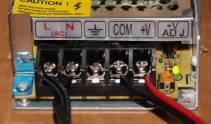 The first two connections identified in red stands for “Live” (or “Hot”) and “Neutral” wires. These are for the input power (120v). The next one is a ground connection for the wall power (if available). As the picture above shows it, the power supply can be powered without a ground connection but it is preferable to protect the unit.
The two next connections labels as “COM” and “+V” stand for the 12v output power. The output connection label as “COM” is the negative side of the 12v. This is where you should connect the negative lead of the LED strip. The output “+V” is the positive side of the 12v.
The section labeled as “+V ADJ” is the output voltage adjustment. It is important to verify with the multimeter that the output voltage is set to 12v (or close to) to prevent damaging the LED strip when connected. An adjustment screw can be turned to set the output voltage appropriately.
Connecting the power cord
Connecting the power cord on the power supply is easy. You need to identify the right wires of the cord and screwing the wires on the right connectors on the power supply. The following identification is valid on North American plug only. The narrow prong on the cord is the “Live” (or Hot) wire. The wider prong is the “Neutral”. The ground pin on the power cord is the longest one. Use the multimeter to identify the matching wire at the other side.
Dimmer connections
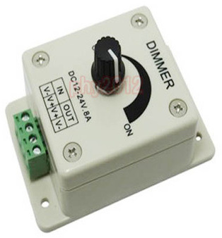 The dimmer has 2 input connections and 2 output connections. The input connections are labeled as “Input V- and Input V+” and output connections are labelled as “Output V+ and Output V-“. I think this is pretty obvious and does not requires any explanations.
Testing everything together
This section defines how to connect all the components together.
Connect the power cord with the power supply. Screw the wires on the power supply as described above. Do not connect the power cord until the complete circuit is assembled.
Connect the positive output of the power supply to one side of the switch. Screw another wire from the other side of the switch to the “IN V+” connector of the dimmer. Get another wire from the dimmer’s “IN V-” back to the power supply negative output.
Connect the dimmer’s “OUT V+ to the positive lead of the LED strip and connect the negative lead of the strip back to the dimmer’s “OUT V-“.
Plug the power cord into the wall, turn on the switch and your LED should turn on. Turn the knob of the dimmer to test the intensity.
Deciding where to put your stuff
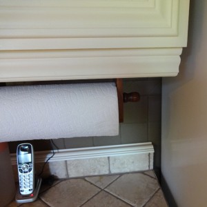
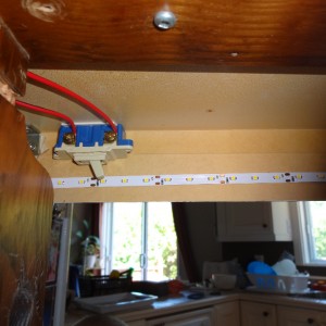
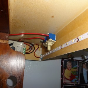
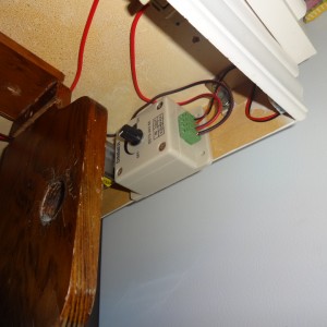
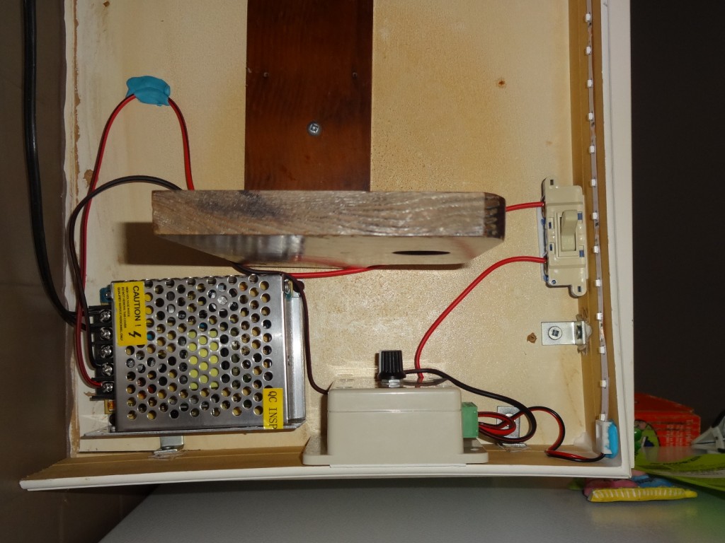
I wanted to position the switch at a location where is can be reached easily with your fingers but I also wanted the switch to be invisible to the eye. I decided to install the switch below the cabinets but hidden behind the front panel under the cabinets. For the same reasons, the dimmer is located at the same location. I used double sided tape to stick the dimmer and the power switch in place. The tape is strong enough to keep the switch in place even when someone is turning the lights on or off.
I also decided to position the power supply below the cabinet, at the back. This location is close to the switch and the dimmer and is also well ventilated. The power supply has two holes for screwing the case to a wood surface. I used small length screws to screw the power to the cabinet’s wood panel.
Here is a view from below the cabinet:
LED strip installation
Cutting
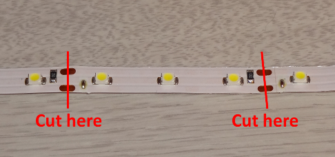 Since I have 3 kitchen cabinets, I had to cut 3 slices of strip. The strip can be cut safely at every 3 LEDs. Each cut point is identified by the contact points in copper.Simply cut in the middle of the contact points to leave enough copper for the 2-pins connectors.
Use a flexible measuring tape to calculate the length of each cabinet and cut a section of the strip for each cabinet sections. If the length of the cabinet does not match a cut point, do not hesitate to get a smaller length since 3 missing LEDs wont make a difference. You just have to center the strip into the cabinet for proper lighting.
Drilling
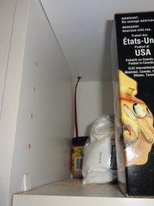
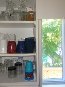
In order to get electricity from one cabinet to another, I had to drill holes in the bottom of the cabinet. This is the only intrusive change that I had to do for this project. I had to drill holes to get the wires above the kitchen hood and above the sink.
Sticking
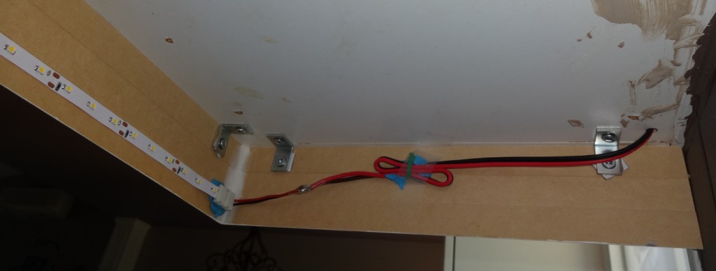 Now is the time to stick the LEDs to the front plate of each cabinet. The opposite side of the LEDs is sticky and can be used to stick the LED to a wall surface. Make sure that the mounting surface is dry and clean since you won’t have multiple tries before the surface loose the ability to stick to the wall. If the strip does not exactly match the length of the cabinet, make sure that you center the strip for appropriate lighting.
Connecting
Use the connectors to link each strip together. The connectors are specifically designed for connecting LED strip together. You just have to open a door, slide the strip in place and close the door which will hold the strip in place. When linking the strip together, make sure that you align the positive (red) and negative (black) leads of the strip with the appropriate color code of the connector.
I decided to use mounting putty gum (“sticker gum”) for holding the connector in place to reduce the weight of the strip on the adhesive surface. The adhesive gum also helps holding the connector wire on the mounting surface instead of seeing the wire hanging below the cabinet.
Final Result
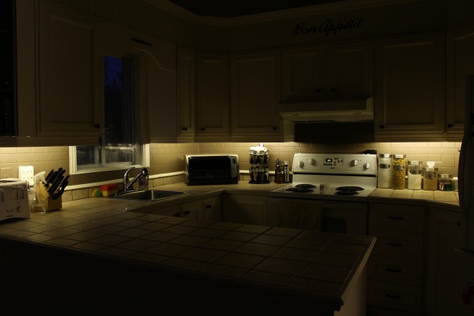
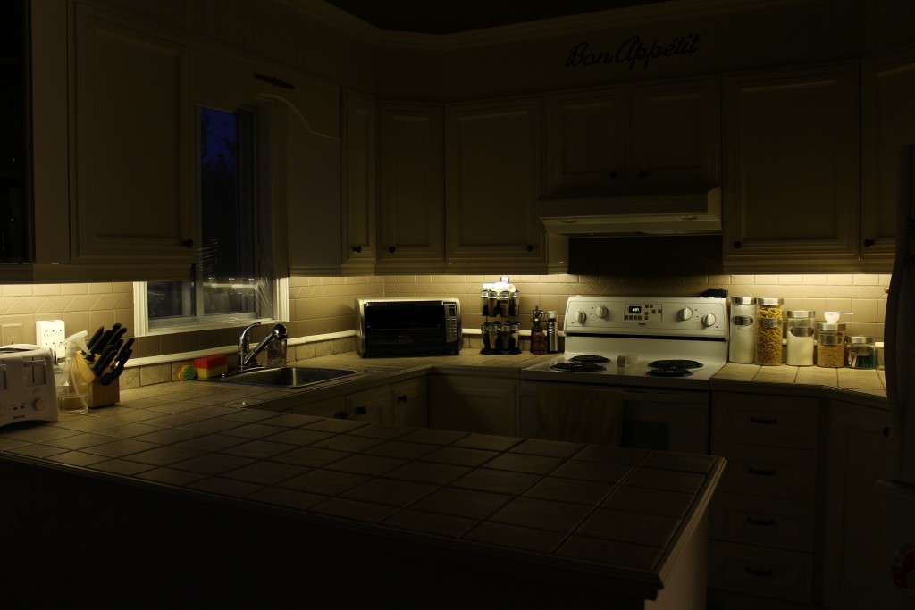
Here is the final result:
Made anything differently?
I do not think that I would make anything differently. Everything is pretty much like the way I wanted. I took my time for preparing this project. I may paint the wires in white sometimes to make them invisible but since I do not see them when I open the cabinet doors, I may leave them as is.
Notes
none
